PREDICTED BEHAVIOUR OF LUMPED ELEMENTS AT FREQUENCIES>10GHz
RG SERIES THIN FILM CHIP RESISTORS SONET SIMULATIONS UP TO 20GHz
| APPLICATION NOTE USM 103 |
Author: Mihaela Radulescu, Ms. Phys. Sc. member technical staff, SEMICONIX CORPORATION |
|
Thin
film chip resistors are physical structures with high power dissipation
capability, small size, optimal and stable operating characteristics at
frequencies as high as 20 GHz. These chip resistors are design to be used in
microwave hybrid circuits for high speed transimpedance amplifiers.
Even a component as simple as a resistor exhibit complex behavior at high frequencies because of different parasitic effects. The simplest RF lumped circuit model for a physical resistor might include a series inductance due to the metal electrodes and a parallel capacitance formed as a result of the ceramic dielectric on which the resistor is constructed. The presence of parasitic inductance and capacitance causes the impedance to depart from a pure, frequency-independent resistance. Very low values of resistance suffer from an early impedance increase, starting approximately at a frequency where the reactance of the series inductance becomes significant compared with the resistance. Similarly, high resistance suffer a premature impedance decrease from the shunt capacitance. The frequency range over which the impedance remains roughly constant is maximized for some intermediate resistance value.
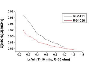
If the resistance equals Zo, the bandwidth Fmax over which the impedance remains approximately constant is given by resonant frequency of the LC combination. The smaller the LC product, the greater the frequency range over which the resistor looks approximately resistive. In order to analyze the behavior of the thin film resistors at high frequencies we use SONNET software for high-frequency electromagnetic analysis Em. It use a modified method of moments analysis based on Maxwell's equations to perform a true three dimensional current analysis of predominantly planar structures. We perform a "full-wave" analysis for thin film resistor geometry, taking into account all possible coupling mechanisms. To model a thin film resistor we use a circuit containing two microstrip transmission lines with the thin film resistor in the middle. The port discontinuity and the transmission line effect are removed from the analysis results by a de-embedding process. The analysis starts by subdividing the circuit metallization into small rectangular subsections. Em automatically places small subsections in critical areas where current density is changing rapidly, but allows larger subsections in less critical areas, where current density is smooth or changing slowly. The automatic algorithm may be modified in order to obtain an analysis time or the required level of accuracy. On the two transmission lines, conductors which are nearly lossless, current travels primarily along the outer edges of the conductor.Thus, enabling edge mesh for these conductors can reduce simulation time with little loss in accuracy. The results of RG series thin film resistors analyses indicate some general rules:
Fig.1. Ratio Z at 0.5 GHz/Z at 20 GHz vs. ratio Lr/Wr for RG1020 and RG1421. |
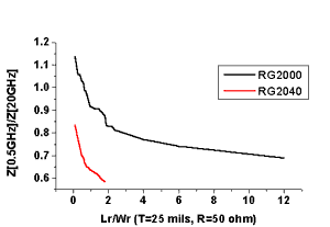
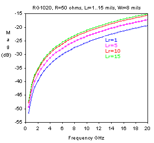
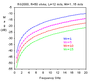
Fig.2.Ratio Z at 0.5GHz/Z at 20GHz for RG2000 and RG2040. The S11 reflection coefficient remains under -20dB for the most geometries of the RG series but increases when the ratio Lr/Wr is increased.(Fig.3,4)
Fig.3. The S11 reflection coefficient for RG1020 , 50 ohm, Wr=8 mils, Lr from 1 to 15 mils.
Fig.4. The S11 reflection coefficient for RG2000, 50 ohm , Lr=12 mils, Wr=1 to 15 mils.
References
1. H.Wheeler "Transmission-line Properties of a Strip on a Dielectric Sheet
on a Plane" IEEE Trans.Microwave Theory Tech. Vol.25, no.8, 1977 |
| US MICROWAVES www.usmicrowaves.com Tel:(408)986-8026 Fax:(408)986-8027 |
| ©1990-2026 US MICROWAVES All rights reserved. No material from this site may be used or reproduced without permission. |


