| APPLICATION NOTE USM 106 | Author: Mihaela Radulescu, M Physic. Sc. member technical staff, SEMICONIX CORPORATION |
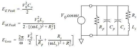
| Quality factor (Q) The efficiency of an inductor is measured by its Q, which is limited by the parasitics. The energy storage and loss mechanisms in an inductor can be described by an equivalent energy model (Fig.1), where Ls, Rs, Rp, and Co represent the overall inductance, conductor loss, substrate loss, and overall capacitance respectively. Fig.1 Equivalent energy model representing the energy storage For an inductor, only the energy stored in the magnetic field is of interest. Any energy stored in the inductor's electric field, because of some inevitable parasitic capacitances in a real inductor, is a loss. Hence, Q is proportional to the net magnetic energy stored, which is equal to the difference between the peak magnetic and electric energies. An inductor is at self-resonance when the peak magnetic and electric energies are equal. Therefore, Q vanishes to zero at the self-resonance frequency. Above the self-resonance frequency, no net magnetic energy is available from an inductor to any external circuit. To be more detail, the inductor Q can be defined as,
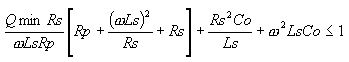
Combining the energy terms in Fig. 2 according to the fundamental definition of Q yields
where wLs/Rs accounts for the magnetic energy stored and the ohmic loss in the spiral conductor. The second term is the substrate loss factor representing the energy dissipated in the substrate. The last term is the self-resonance factor describing the reduction in Q due to the increase in the peak electric energy with frequency and the vanishing of Q at the self-resonant
frequency. We can therefore specify a minimum required quality factor. We may also maximize the quality factor by maximizing Qmin subject to constraint (3). Minimum self-resonance frequency. The self-resonance frequency wsr is the frequency at which the quality factor Q is zero A condition on minimum self-resonance frequency wsr ³wsr;min, can be written as the posynomial inequality
Therefore we can handle a specification on minimum self-resonance frequency and we can maximize the self-resonance frequency (by maximizing subject to constraint (4) ). Optimal design of inductors A common problem in inductor design is to maximize the quality factor for a given inductance value and for a minimum self-resonance frequency. Other constraints may be added (such as the minimum spacing and turn width, the maximum area available, the maximum parallel capacitance, etc.). The point is that the design problem can be formulated as a geometric program. Geometry constraints The monomial inequalities W>Wmin and s>smin handle the processing constraints that limit the minimum feature size. The inductor area can be constrained or minimized using the monomial inequality, p(Dout/2)2<=Amax. |
|
 (3)
(3)