FLIP CHIP RESISTORS - MICROWAVE THIN FILM CHIP RESISTORS for f >20GHz APPLICATIONS -20GHz - thin film resistors for microwave and transimpedance amplifiers for optical communication receivers RG5000-xx-FC The RG5000-xx-FC series of microwave thin film chip resistors is designed to be used in microwave hybrid circuits for biasing of active components and as feedback resistors for high speed transimpedance amplifiers for optical communication receivers. To attain very low capacitance to ground, these chip resistors are manufactured on 10 mils Al2O3ceramic substrates and do not have backside metallization. In addition of the regular RG5000-xx series, RG5000-xx-FC has a protective dielectric coating that prevents shorting due to the conductive epoxy.These devices are specifically designed and manufactured to be compatible with flip chip conductive epoxy mounting. These devices can be used over the full military temperature range -55°C to +125°C. Quality and workmanship is per MIL-S-883. Devices are 100% tested, visual inspected and packaged in waffle packs. US Microwaves employs proprietary thin film technologies for deposition of a wide range of sheet resistance films from 1W/sq to 10,000 W/sq.Custom lab kits are available: RG Lab kit.The resistive material is high stability Tantalum Nitride with low temperature coefficient of resistance, <75ppm/°C typical. For Rsq<10W/sq and Rsq>500W/sq, the resistive material is proprietary.The bonding pads of the resistors are 3m m thick, 99.99% electroplated gold with a TiW barrier that withstands 30 min at 400°C in air without loss of adhesion. The backside of the die is NOT metallized. Standard TiW/Au or other custom metallizations are available upon special request. |
|
FLIP CHIP RESISTORS - MICROWAVE THIN FILM CHIP RESISTORS
|
20GHz - thin film resistors for microwave and transimpedance amplifiers for optical communication receivers RG5000-FC |
The RG5000-FC series of microwave thin film chip resistors is designed to be used in microwave hybrid circuits for biasing of active components and as feedback resistors for high speed transimpedance amplifiers for optical communication receivers. To attain very low capacitance to ground, these chip resistors are manufactured on 10 mils Al2O3ceramic substrates and do not have backside metallization. In addition of the regular RG5000-xx series, RG5000-xx-FC has a protective dielectric coating that prevents shorting due to the conductive epoxy. |
These devices are specifically designed and manufactured to be compatible with flip chip conductive epoxy mounting. These devices can be used over the full military temperature range -55°C to +125°C. Quality and workmanship is per MIL-S-883. Devices are 100% tested, visual inspected and packaged in waffle packs. US Microwaves employs proprietary thin film technologies for deposition of a wide range of sheet resistance films from 1W/sq to 10,000 W/sq. |
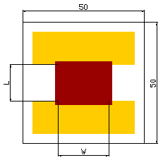
R=0.1 to 3.5 sq |
Custom lab kits are available: RG Lab kit |
R(W) | USM Part # | R(W) | USM Part # | R(W) | USM Part # |
1.0 | RG5000-1P0-FC | 10 | RG5000-10P0-FC | 100 | RG5000-100P0-FC |
1.2 | RG5000-1P2-FC | 12 | RG5000-12P0-FC | 120 | RG5000-120P0-FC |
1.5 | RG5000-1P5-FC | 15 | RG5000-15P0-FC | 150 | RG5000-150P0-FC |
1.8 | RG5000-1P8-FC | 18 | RG5000-18P0-FC | 180 | RG5000-180P0-FC |
2.2 | RG5000-2P2-FC | 22 | RG5000-22P0-FC | 220 | RG5000-220P0-FC |
2.7 | RG5000-2P7-FC | 27 | RG5000-27P0-FC | 270 | RG5000-270P0-FC |
3.3 | RG5000-3P3-FC | 33 | RG5000-33P0-FC | 330 | RG5000-330P0-FC |
3.9 | RG5000-3P9-FC | 39 | RG5000-39P0-FC | 390 | RG5000-390P0-FC |
4.7 | RG5000-4P7-FC | 47 | RG5000-47P0-FC | 470 | RG5000-470P0-FC |
5.0 | RG5000-5P0-FC | 50 | RG5000-50P0-FC | 500 | RG5000-500P0-FC |
5.6 | RG5000-5P6-FC | 56 | RG5000-56P0-FC | 560 | RG5000-560P0-FC |
6.8 | RG5000-6P8-FC | 68 | RG5000-68P0-FC | 680 | RG5000-680P0-FC |
7.5 | RG5000-7P5-FC | 75 | RG5000-75P0-FC | 750 | RG5000-750P0-FC |
8.2 | RG5000-8P2-FC | 82 | RG5000-82P0-FC | 820 | RG5000-820P0-FC |
SUBSTRATE INFORMATION | RESISTOR SPECIFICATIONS | |||||
Material |
Thickness (mils) |
Die size (mils) |
Power rating (mW@70°C) |
Tolerances (q%) |
Capacitance (pF) |
RC constant (sec) (R=1kW) |
Al2O3, 99.6% | 10±1 | (50±2)x(50±2) | 762 | 1, 5, 10 | 0.136 | 1.36E-10 |
PROCESS INFORMATION | ||
Resistor | Conductor | Backside metallization |
The resistive material is high stability Tantalum Nitride with low temperature coefficient of resistance, <75ppm/°C typical. For Rsq<10W/sq and Rsq>500W/sq, the resistive material is proprietary. | The bonding pads of the resistors are 3m m thick, 99.99% electroplated gold with a TiW barrier that withstands 30 min at 400°C in air without loss of adhesion. | The backside of the die is NOT metallized. Standard TiW/Au or other custom metallizations are available upon special request. |
ORDERING INFORMATION RG5000-xxPx-FC-q% |
US MICROWAVES www.usmicrowaves.com Tel:(408)986-8026 Fax:(408)986-8027 |
©1990-2024 US MICROWAVES All rights reserved. No material from this site may be used or reproduced without permission. |